
Building Your First CubeSat Model: A Beginner's Roadmap for Engineering Undergrads
Building a CubeSat model is one of the most rewarding hands-on experiences an undergraduate engineering student can pursue. It transforms abstract classroom theories into tangible hardware and flight software. Navigating the world of miniaturized satellite design requires clear guidance, structured workflows, and proven strategies. This comprehensive beginner’s roadmap details everything needed to take a 1U CubeSat model project from concept to physical reality.
1. Introduction to CubeSat Model Building for Undergrads
Entering the field of small satellite development begins with understanding standard form factors. A basic 1U CubeSat model measures precisely 10 centimeters on each side, serving as the foundational building block for modern picosatellite engineering. For undergraduate engineering students, building a scale or functional prototype offers a low-cost entry point into aerospace engineering without requiring an immediate orbital launch budget.
Starting with a physical desktop model helps students grasp spatial layout, structural constraints, and functional subsystem integration. By constructing an engineering model, student teams learn to manage volume limitations, thermal paths, and component layout before committing to expensive space-grade hardware. Detailed references on standard form factors are maintained by the Cal Poly CubeSat Program.
2. Core Subsystems in a CubeSat Model Design
Every functional satellite model consists of core internal modules that work in harmony. Understanding these basic building blocks is essential for effective hardware selection and system design:
Structure Subsystem: The outer mechanical frame that holds all internal components securely.
Electrical Power Subsystem (EPS): Manages energy gathering through solar panels and balances power distribution via onboard batteries.
On-Board Computer (OBC): Serves as the central brain processing operational commands, gathering diagnostic telemetry, and coordinating tasks.
Attitude Determination and Control System (ADCS): Manages spatial orientation, using magnetorquers, reaction wheels, or simple passive magnet systems.
Communications (COMM): Transmits payload data and telemetry down to a ground station while receiving operational commands.
Payload: The primary experiment or instrument onboard, such as a camera or radiation sensor.
Balancing the power, mass, and data consumption across these modules forms the core challenge of satellite engineering.
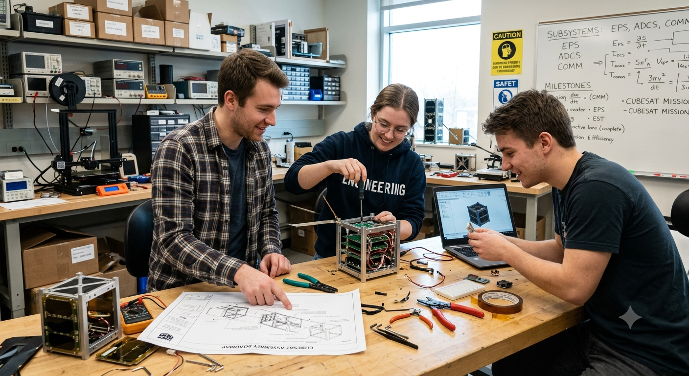
3. Selecting Hardware and Materials for CubeSat Prototyping
Developing an initial 1U prototype does not require vacuum-certified materials right away. Engineering undergraduates can utilize affordable, off-the-shelf consumer electronics to prove their concept:
| Subsystem Component | Prototype Hardware Choice | Flight Model Hardware Equivalent |
| Microcontroller (OBC) | Arduino Mega, ESP32, or Raspberry Pi | ARM Cortex-M4 Space-grade OBC |
| Structural Frame | 3D Printed PETG / ABS or Extruded Aluminum | Anodized Aluminum 6061-T6 |
| Power Management | Custom Li-ion TP4056 Module with Solar Cells | Space-Qualified EPS with MPPT |
| Sensors | MPU6050 IMU & BMP280 Environment Sensor | Tri-axial Gyroscopes & Sun Sensors |
| Radio Link | LoRa Transceiver (433/915 MHz) or NRF24L01 | UHF/VHF Transceiver Board |
Utilizing 3D printers and modular development boards accelerates iteration speed while keeping team costs low. Architectural design templates and open-source hardware options are cataloged at CubeSat Resources.
4. CAD Modeling and Structural Layout Strategy
Mechanical design starts in Computer-Aided Design (CAD) software like Fusion 360 or SolidWorks. Designing the structural frame requires strict adherence to standardized rail dimensions to ensure potential compatibility with standard deployers.
+-------------------------------------------------------+
|                CUBESAT MODEL LAYOUT                   |
|                                                       |
|   +-----------------------------------------------+   |
|   |         Solar Panels (External Walls)         |   |
|   +-----------------------------------------------+   |
|   |  [COMM] Radio Transceiver & Deployable Ant  |   |
|   +-----------------------------------------------+   |
|   |  [OBC] Microcontroller & Sensor Stack         |   |
|   +-----------------------------------------------+   |
|   |  [EPS] Power Management & Battery Pack        |   |
|   +-----------------------------------------------+   |
|   |  [PAYLOAD] Camera / Secondary Experiment      |   |
|   +-----------------------------------------------+   |
+-------------------------------------------------------+
Students should arrange internal PCBS using standardized PC/104 stackable headers or custom backplane buses to avoid messy internal wiring harnesses. Keeping the Center of Mass near the geometric center of the chassis is critical for physical stability.
5. Electrical Wiring and Power Budgeting
A successful satellite model relies on strict energy accounting. Students must compute a detailed power budget tracking every milliamp consumed by the OBC, sensors, and radios during active and idle operational modes.
To prevent battery depletion, the Electrical Power Subsystem must charge the onboard lithium-ion cells effectively during simulated sunlit phases. Safety mechanisms—such as deployment switches that cut master power until the model is released—serve as crucial design practices for real-world mission safety.
6. Developing Software and Telemetry Protocols
The software architecture of a satellite model handles task scheduling, sensor sampling, power monitoring, and telemetry radio transmission.
+------------------+      +-------------------+      +--------------------+
|  Read Sensors    | ---> | Pack Telemetry    | ---> | Send Radio Packet  |
|  (IMU, Temp, V)  |      | Format Struct/JSON|      | Transmit Ground Link|
+------------------+      +-------------------+      +--------------------+
         ^                                                     |
         |                                                     v
+------------------+      +-------------------+      +--------------------+
| Sleep / Low Power| <--- | Process Commands  | <--- | Listen for Downlink|
| Save Battery     |      | Check Ground Cmds |      | Ground Station Check|
+------------------+      +-------------------+      +--------------------+
Writing modular, non-blocking code ensures the microcontroller can read internal sensors while concurrently listening for incoming ground commands. Developing a simple ground-station dashboard using Python or Node-RED allows teams to visualize live diagnostic telemetry in real time. Official guidelines for small satellite software planning are hosted by the NASA Small Spacecraft Systems Virtual Institute (S3VI).
7. Assembling and Integration Testing (FlatSat Setup)
Before mounting hardware into a compact chassis, the entire system should be assembled flat on a workbench—a configuration known as a FlatSat.
Layout all microcontrollers, power boards, radios, and sensors flat on an anti-static mat, using jumpers to simulate internal connections.
Apply power through a regulated bench supply, confirming stable voltage lines (3.3V, 5V) across all subsystem interfaces before connecting batteries.
Run end-to-end communication tests by triggering sensor readings and capturing radio downlink signals on a local ground terminal.
Mount the verified PCB stack inside the 3D-printed or aluminum 1U chassis, securing all standoffs and routing solar panel wiring cleanly.
Integrate subsystems step-by-step rather than all at once to easily isolate electrical short circuits or communication errors.
8. Environmental Simulation and Functional Verification
To simulate real operational conditions, undergraduate teams should submit their complete prototype model to basic environmental and functional tests:
Thermal Testing: Place the model inside a controlled thermal chamber or oven to verify component behavior under hot and cold extremes.
Vibration Analysis: Perform shake testing on a low-cost shaker table to identify loose mechanical fasteners or fragile solder joints.
Radio Range Checks: Conduct line-of-sight communication tests over long outdoor distances to calibrate antenna performance and packet reception rate.
Drop and Deployment Testing: Test mechanical deployment switches and spring-loaded solar panel mechanisms to confirm reliable activation.
Documenting test results establishes rigorous system engineering practices early in an undergraduate’s career.
9. Conclusion and Next Steps for Engineering Teams
Building a functional 1U CubeSat model bridges academic theory and real-world aerospace engineering. Through hands-on design, CAD modeling, power budgeting, and embedded software development, undergraduate students gain invaluable experience in multi-disciplinary systems engineering.
Once your team successfully operates a desktop prototype, consider competing in national university satellite initiatives or scaling up your concept toward a space-ready flight model.

How useful was this post?
Click on a star to rate it!
Average rating 0 / 5. Vote count: 0
No votes so far! Be the first to rate this post.